In modern life, people pay more and more attentions to the aerial insulated conductor because of its good insulating property. However when conductor encounter lightning strikes, the overvoltage will firstly puncture the insulating layer and then cause the flashover. The broken-down layer will have a pinhole.As the continuous power frequency and short-circuit current is blocked by the surrounding insulator, the arc root can only be burned in the pinhole area which will damage conductor in a very short period of time. Besides, the insulator may also occur the flashover and explosion, and even cause the wire fuse. If no proper lightning proof measure is taken for the insulated conductor, it will not only affect the project quality and operating management, but also will cause a lot of accidents. The emergence of lightning proof fittings effectively resolve the above problems.
Principle and Features
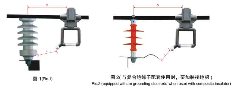
The lightning proof grounding clamp for insulated overhead conductors has the structure of the common grounding clamps, but it also has an outer gap discharge device. In the top, the puncture electrode could penetrate through the insulation, which leads to the electrical connection between the ground clamp and the conductor and also could connect the line to ground by hanging up a ground rod in the line maintenance. In the bottom, an arc electrode at the lateral angle of grounding ring, and the steel pin of post insulator form a discharge gap (if used with the composite insulator or other insulator, here should install a grounding electrode).
ln the normal operation, no current passed through because of large air gap between the arc electrode and insulator pin. When lightning occurs, once the lightning voltage is over certain value or faced thunderstorm, the flashover happened between the arc electrode and grounding electrode (or insulator pin) which will cause a short circuit ring. The continuous frequency arc will be burned between the arc electrode and grounding electrode or steel pin,to release the overvoltage energy and protect the wires from damage.
Our lightning proof grounding clamp adopts unique piercing teeth and arc design .No stripping the insulated layer when installation water inled and corrosion will be avoided. Installation is extremely easy, which greatly reduces the labor intensity. It has great promotional value.
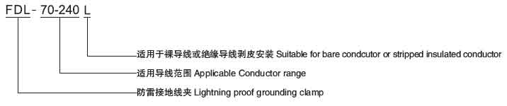
Model instrucition
Specifications and technical parameters
|
Cat.No.
|
Clamping Range
|
Conductor Range(mm2)
|
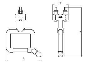
Dimension(mm)
|
Conductor Dia.
|
|
A
|
B
|
C
|
|
FDL70~240
|
Φ16~27
|
JKLY-70~240
|
165
|
76
|
232
|
Φ10~Φ19
|
|
FDL70~240L
|
Φ16~27
|
LGJ/LGJF-70~240
|
165
|
76
|
232
|
Φ10~Φ19
|
Applicable insulators and installation parameters
|
Insulator type
|
P-10T
|
P-15T
|
FPQ3-10
|
PS15
|
P-20T
|
FPQ4-10
|
|
Distance D(mm)
|
270±10
|
270±10
|
270±10
|
270±10
|
270±10
|
270±10
|
|
Distance L(mm)
|
105±10
|
140±10
|
135±10
|
150±10
|
165±10
|
170±10
|
Installation instruction:
1. Install the lightning proof grounding clamp on the load side of insulator, and determine the distance (D) between the grounding clamp and the center of insulator according to table 1.
2. Loosen the pressure cover, and put the conductor into the groove, note that the arc electrode should be toward to the insulator.Adjust the distance D according to table 1.Then alternating symmetrically tighten the torque nut by torque wrench until the head of torque nut sheared off.
3. Loosen the nut of insulator pin, and then insert the fork entry of grounding plate into the gap of insulator base and tower cross- arm, The striking arc arm will be under the conductor and arc electrode. Adjust the plate extended distance to make the distance L consistent with the table 1.
4. Equipped the grounding clamp with insulator cover, and buckle the fasteners and then the installation is complete.
Notes:
1.Lines shall be inspected before and after rainy season and checked whether the product is installed in a normal state, or damaged. If necessary, to adjust or replace the equipments.
2.If an automatic reclosing protection equipment is installed at line starting side, adjust the parameters to effectively reduce line interruption frequency.
|